
By Halcyon Machinery · Editorial review ·
Direct answer. A shared tray section may be formed on one proposed line, but perforations are a separate production requirement. Do not infer punching from a photograph of the forming rolls. Ask for the exact solid-bottom and perforated drawings, a station-by-station scope, a documented no-punch mode, and accepted trial pieces for both products. The supplier must show how holes, cut lengths and changeovers work in the configuration being quoted.
Start with the cable-support design, not the machine name
Solid-bottom and perforated trays are different finished products even when their sidewall and lip drawings look similar. An Eaton product example distinguishes continuous support from a solid bottom and attachment or heat-dissipation opportunities in a perforated bottom. Those are examples of product functions, not permission to use Eaton's dimensions or performance claims for another system. The responsible designer must select the tray type for the cables, installation environment, support method and applicable project requirements.
Give the machine supplier a revision-controlled drawing for each tray. State the base width, side height, lip, bend radii, material grade, thickness range, coating, cut length and intended splice or cover. For the perforated version, add hole shape, size, pitch, edge and end distances, datum, unpunched zones and allowable burr condition. Do not call two profiles interchangeable until those drawing features have been checked.
Make the punching and bypass scope explicit
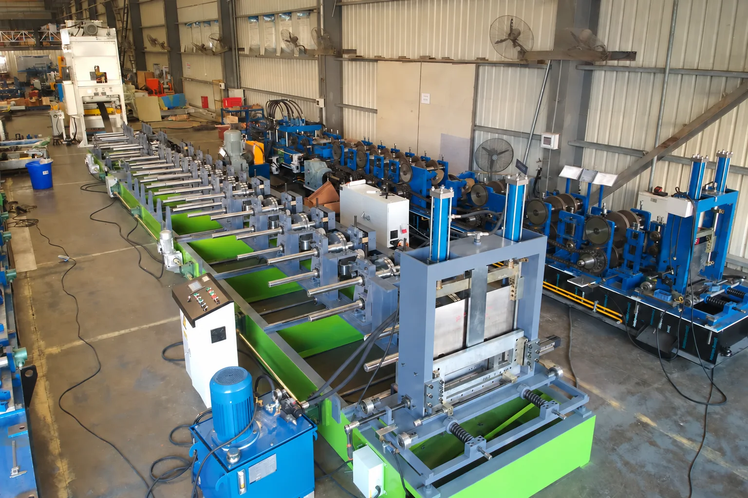
Request a layout showing coil feed, any levelling, punching, forming, cut-off, scrap removal, controls and run-out. Where the supplier proposes one line for both products, ask which tooling stays installed, which punches are disabled or bypassed for solid-bottom orders, how the program prevents unwanted holes, and what has to be reset during changeover. Also ask whether cover, bends, tees and splice plates are separate equipment or purchased accessories. A published HCT-600 line is one named production reference; its advertised dimensions or speed are not a guarantee for these two drawings or a current Halcyon proposal.
If the supplier offers only the formed channel, price and acceptance must exclude unquoted punching or joining operations. If perforation is included, identify the die set, hole map, reference edge, allowable scrap and maintenance access. A line that can form a tray is not automatically a complete cable-support-system factory.
Trial both modes with traceable samples
Agree the test material, drawing revision and trial lengths before a demonstration. Run a labelled solid tray and a labelled perforated tray at the proposed settings. Record section width and height, lip geometry, cut length and visible coating condition on both. On the perforated part, measure holes from the agreed datum, note edge burrs, and check that cut ends do not interrupt the specified end distance. On the solid part, verify that no unintended holes or marks remain after any bypass. Test a changeover and repeat samples if the quote claims both modes.
Then check the specified splice, cover and hold-down parts against the samples. The separate slot and splice-fit trial guide explains that assembly test in more detail. Neither trial establishes an installed tray system's load rating, electrical suitability or corrosion life; ask the responsible designer for the applicable system evidence.
What to send for a comparable quotation
| Buyer input | What it resolves |
|---|---|
| Solid and perforated tray drawings, with revisions | Whether the forming section and tooling can be shared. |
| Steel grade, coating, thickness range and coil width | The material for the proposed forming and punching trials. |
| Hole geometry, pitch, datum and unpunched zones | Punching method, die set and cut-end control. |
| Splices, covers, fittings and project support requirements | Which accessories need separate production and evidence. |
| Target accepted output and product-change frequency | The test sequence and changeover scope to verify. |
Compare the cable tray equipment page with your controlled drawings. Send both tray drawings, the punching layout, material and target output through the enquiry form; Halcyon Machinery will carry out a machine-specific scope review with our factory team before any performance claim is agreed.
Frequently asked questions
Does a roll forming machine automatically make perforations?
No. The proposed line must explicitly include the punches, dies, controls and scrap handling needed for the approved hole pattern; roll forming alone establishes the section.
Can the same tooling make solid and perforated trays?
A common forming section may be proposed for a shared cross-section, but the supplier must demonstrate the no-punch mode, perforated mode, changeover and accepted samples for each approved drawing.
Does a trial tray prove installed load capacity?
No. A machine trial checks the specified section and features. Support spacing, loading, cable retention and system approval require evidence from the responsible cable-support designer.
Sources and limits: Eaton's pan-tray page distinguishes solid and perforated product functions; HCT-600 page is a named cable-tray line example. Neither source establishes the offered Halcyon configuration, installed performance or a customer result. Editorial review: Halcyon Machinery, 1 October 2026.
Send tray drawings