
By Halcyon Machinery · Reviewed
Direct answer. Give the machine supplier the approved tray section, hole drawing, splice plate, cover and fasteners together. Trial parts made with the agreed material and configuration. Measure slots from the same drawing datum used by the mating plate, then physically assemble a representative splice and cover. A perforated tray that looks correct in a photograph can still fail at the joint.
Define the mating system before selecting the line
Start with a drawing revision for each tray width and side height. Mark the slot size and pitch, reference edge, end distance, bend radii, joining method and any unpunched zones. Supply the actual splice plate, fasteners and cover or their controlled drawings. Cable-tray systems differ in these details; a machine catalogue photograph is not a substitute for the buyer's chosen system. The cable tray machine page explains the scope questions for tray, ladder, trunking and cover sections. The industry examples in the Legrand P31 sheet illustrate that slot and section layouts are product-specific; their dimensions must not be copied into another customer's tooling without approval.
Agree how the first-off and repeat parts will be checked
The buyer and our factory team should agree on material grade, coating, thickness range and trial length before the test. On the first-off part and later samples, record section width and height, flange and lip form, slot position from the approved datum, slot-to-slot pitch, cut length and condition of punched and cut edges. Photograph the measurement setup and label the samples by drawing revision. If the line makes multiple widths, test each quoted changeover condition rather than assuming the first setup covers all widths.
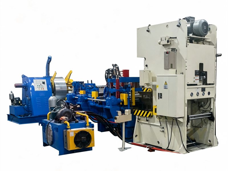
The location of punching relative to forming, the number of tool sets and the scrap-handling arrangement depend on the proposed design. An HCT-600 example from our Xiamen production base shows one process route, not a universal Halcyon specification. Ask for the actual line layout and module list in the quotation.
Assemble the joint, not just the tray
Put two trial tray ends and the specified splice plate together with the approved fasteners. Check that the end distances allow the plate to seat, the holes align without forcing the bolts, the mating edges do not create an unintended gap or burr interference, and the cover fits where one is specified. Record what was measured and what was observed separately. The fitting trial may reveal a drawing, punching or cut-off problem, but does not establish an installed system's load rating, electrical continuity or corrosion performance. Those require the responsible system designer's applicable evidence.
| Buyer question | Trial evidence | Limit |
|---|---|---|
| Do the slots align with the splice? | Labeled tray, plate, fasteners and hole measurements from agreed datums | One sample does not establish repeatability |
| Does the cover fit? | Assembly check for each quoted tray-and-cover pair | A cover photo does not establish fit across all widths |
| Are the cut ends usable? | End-distance and edge-condition record on repeat parts | Does not establish installed load performance |
| Can the proposed line make all variants? | Tool-set list, changeover steps and trial samples for quoted variants | A different maker's catalogue is not the accepted offer |
Questions buyers ask
Is a measured hole pitch enough? No. The end distance, reference edge, section shape and actual splice hardware also affect assembly.
Can a tray and its cover always use the same rollers? No. Compare each approved section and ask our factory team to identify the required tooling and changeover scope.
Does the machine trial certify the cable-support system? No. It verifies agreed formed parts and their fit under the recorded trial conditions. System design and compliance are separate decisions.
Request a project-specific trial plan
Send the tray and cover profile drawings, steel grade, coating, thickness range, punching layout, splice and fastener details, target output and intended application. Ask Halcyon to confirm the proposed modules and sample plan with our factory team. Send the drawing package.
Source and review: Halcyon Machinery buyer-review framework, reviewed 29 September 2026; relevant product-system context from Legrand P31 and a process example from HCT-600. This article does not claim that a particular Halcyon-quoted machine has passed the trial described here.
Send your drawing for a technical review