
One production workflow
Forming, transfer and assembly stations are planned around the required building or module output.
Integrated production of light steel components for wall, floor and roof modules. The final tooling, layout and guaranteed output are confirmed after we review your profile drawing and production target.
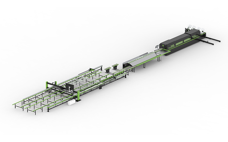
Reference configuration. Final machine follows the signed technical agreement.
The engineering starts from the part, material, tolerances, operations, production data and required output.
Forming, transfer and assembly stations are planned around the required building or module output.
Production information is organized from member creation through identification and assembly.
Stations can be introduced in phases to match factory space and investment timing.
Mechanical, electrical and data interfaces are documented for the complete line.
Values below separate confirmed product information from project-dependent engineering data.
Reference-data rule: published figures describe a documented reference configuration. Power, speed, tooling, dimensions and guaranteed accuracy become binding only when repeated in the signed technical agreement for your project.
Check the route from approved building data to individual members, identification, transfer, assembly and inspection. Ask which stations are included in this quotation and which handoffs remain manual.
Before approving an integrated line, request a quotation-specific layout, station list, member identification method, mechanical and data handoffs, and sample inspection plan. A reference photograph alone cannot verify the proposed scope.
Forming, transfer, fixtures, fastening and software are separate scope decisions. Compare what is included, excluded and to be integrated by the buyer against the planned building mix and shift pattern.
Machine families selected for the required wall, floor and roof members.
Conveyors, AMRs or robot handling between production stages.
Wall, truss or module fixtures sized to the project envelope.
Manual, assisted or automated screw and connection systems.
Scheduling, part identification and progress tracking interfaces.
Line modules grouped into practical installation and training stages.
Integrated production of light steel components for wall, floor and roof modules.
Send the wall, floor and roof member schedule, representative section drawings, steel grades and thicknesses, connection details, planned building mix, shift pattern and available factory floor plan. Mark any information that is still provisional.
No fixed module list can be inferred from the system name. Request a station-by-station scope showing included equipment, manual steps, third-party interfaces, utilities, guarding and software responsibilities.
Use an agreed mix of members or modules and a defined shift. Ask for the time assumptions at forming, transfer, assembly and inspection, then identify the bottleneck and the acceptance method. A forming-line speed alone is not complete-system output.
Review a quotation-specific layout, interface list, identification and data flow, representative member samples, inspection criteria, installation stages and a test plan for the offered configuration.
Share member drawings, material data, connection details and the floor plan so the proposed forming-to-assembly route, station boundaries and acceptance checks can be reviewed against your project.